2 Pin Flasher Relay Wiring Diagram
Led flasher relay 5 pin ep27 fix hyper flash decoder load equalizers turn signal. 3 pin led flasher relay wiring diagram a newbie s.

2 Pin Flasher Relay Wiring Diagram — UNTPIKAPPS
Its easy factory switch most of you will have a hotrod that uses a steering column that has a.
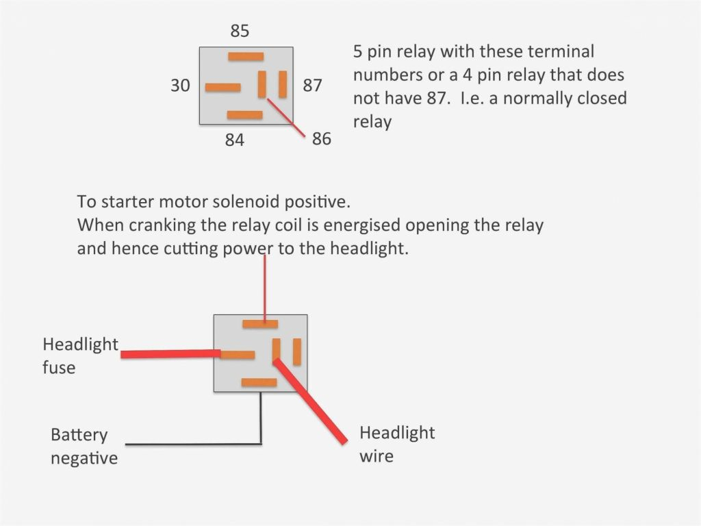
2 pin flasher relay wiring diagram. Simple relay flasher circuit with ne555 timer. 45 new driving light relay wiring diagram a govern relay is used in the automotive industry to restrict and bend the flow of el in 2021 diagram relay electronic parts. It includes guidelines and diagrams for various types of wiring strategies and other things like lights, home windows, and so forth.
60 to 120 flashes per minute. 60 to 120 flashes per minute. Make your own switch system.
Not merely will it help you attain your desired results quicker, but also make the complete procedure less difficult for everybody. 5 pin spdt relay wiring diagram 12 volt 5 pin relay diagram wiring for 5 pin bosch relay wiring diagram, image size 650 x 650 px, image source : 4 pin flasher relay wiring diagram.led turn signals flasher relays and diode kits adventure.
Turn sugnal flasher unit sprint headlight relay serial flashers mga 1500 or 1600 with switch lucas 33117d xk jag electronic version of sfb162 12v 98w 4 pin hazard indicator mgb electrical advices and wiring relays a. 2 pin flasher relay wiring diagram | my wiring diagram the terminal widths used on 4 and 5 pin relays are almost always 6.3mm wide, however some more specialist relays can have terminal widths of 2.8mm, 4.8mm and 9.5mm. Flash rate is electronically controlled.
Wiring diagram 2 pin flasher relay. A wiring diagram is a simplified conventional photographic depiction of an electric circuit. Here is my understanding of the pinout below.
The 9.5mm wide terminals tend to be used for higher power applications (such as for starter motor solenoid activation) and the. Steady flash rate for all led and incandescent loads. Otherwise, the structure will not function as it ought to be.
Injunction of two wires is usually indicated by black dot at the intersection of 2 lines. According to previous, the traces in a 2 pin flasher relay wiring diagram signifies wires. I've looked all over the internet for a clear diagram, and i only come across the following one.
The relay works opposite (high means low for relay). 5 pin flasher relay wiring diagram source: A simple construction procedure of a motorcycle electronic 2 pin turn signal indicator with beeper circuit has bee circuit projects.
With such an illustrative guide, you’ll be capable of troubleshoot, stop, and complete your tasks easily. Each part should be placed and connected with different parts in particular manner. Relay has either 4 or 5 pins, but in this flasher relay, there will be 2 or 3 pins.
The flasher receives power from one of 2 fuses, depending on whether or not the hazard switch is operated. Www.untpikapps.com read 6 volt positive ground generator wiring diagram database before reading the. Wiring diagram arrives with numerous easy to stick to wiring diagram guidelines.
These instructions will likely be easy to comprehend and use. By admin | october 21, 2017. However, it doesn’t mean connection between the cables.
2 pin flasher relay wiring diagram wiring diagram is a simplified pleasing pictorial representation of an electrical circuit. The 9.5mm wide terminals tend to be used for higher power applications (such as for starter motor It contains instructions and diagrams for different kinds of wiring strategies as well as other things like lights, windows, etc.
There’ll be primary lines that are represented by l1, l2, l3, and so on. 3 pin led turn signal flasher relay mgi sdware. Fits in round flasher socket.
Externally, the only difference is in the connection for the dash indicator. Ideal for vintage cars and trucks. 2 pin relay wire diagram from how to wire a 3 prong flasher source h2o turbo gitarrenapotheke de 3 pin 2 cb wire diagram wiring diagram blog from how to wire a 3 prong flasher source 15 bngh eat and shape de plug wiring.
We never store the image file in our host. Actually we have been remarked that 3 pin flasher unit wiring diagram is being just about the most popular field right now. Koso 3 pin flasher relay 12 v 1 w 80 louis motorcycle clothing and technology.
It is intended to aid each of the average person in developing a correct program. 2 pin motorcycle turn signal flasher indicator circuit with beeper homemade projects. It shows the components of the circuit as simplified shapes, and the capacity and signal friends amongst the devices.
At times, the cables will cross. 2 pin flasher relay wiring diagram rainbowlolipoplife. 2 pin flasher relay wiring diagram | my wiring diagram the terminal widths used on 4 and 5 pin relays are almost always 6.3mm wide, however some more specialist relays can have terminal widths of 2.8mm, 4.8mm and 9.5mm.
Automotive flashers gtsparkplugs adjule flasher relay led 2 pin mgi sdware thesamba com beetle 1958 1967 view topic wiring for a g circuit suggestions grote industries turn signals signal using relays factory five racing forum cf12anl 01 electronic fix bulbs hyper flash. This diagram shows the turn signal flasher circuit in its simplest form:
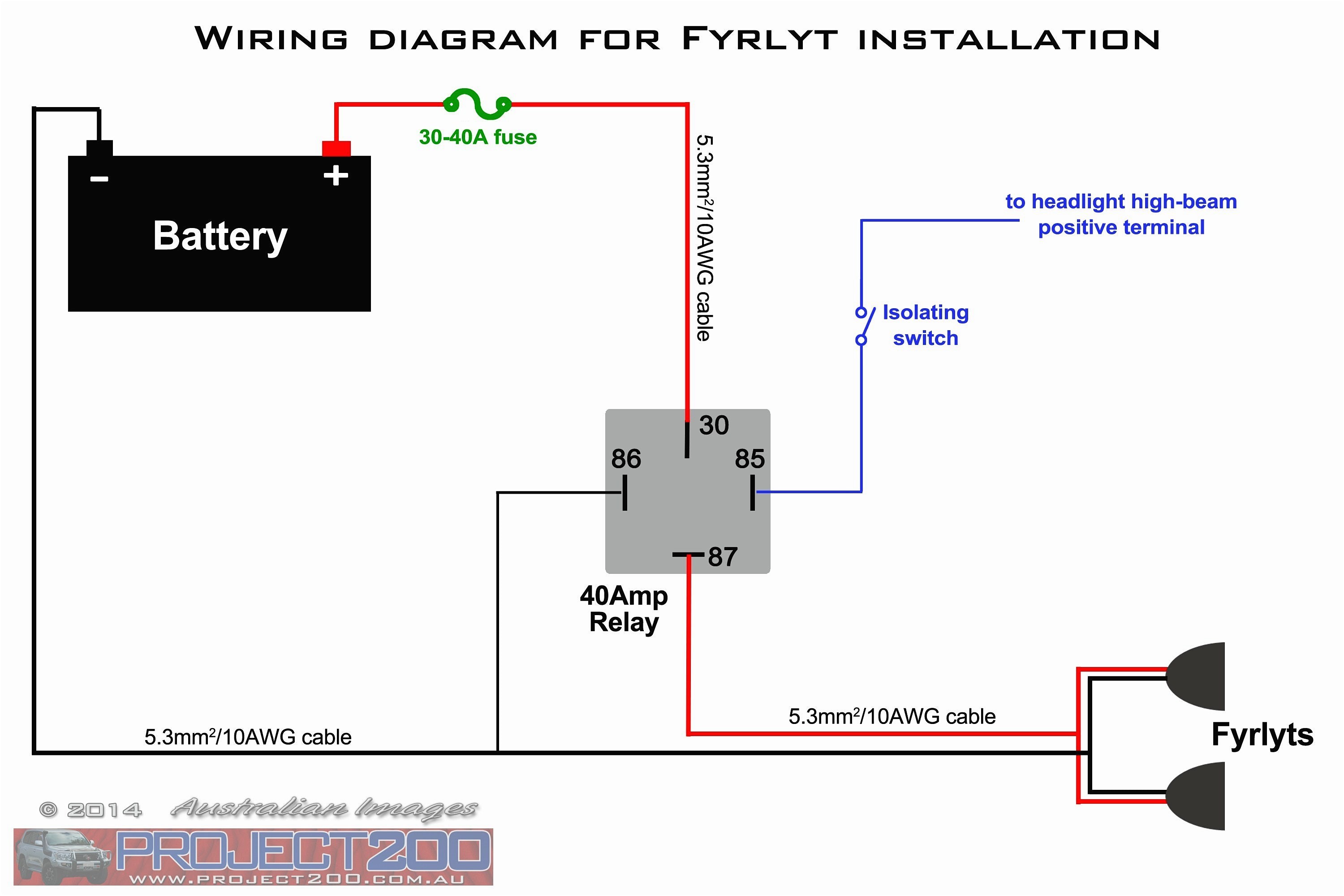
2 Pin Flasher Relay Wiring Diagram My Wiring DIagram
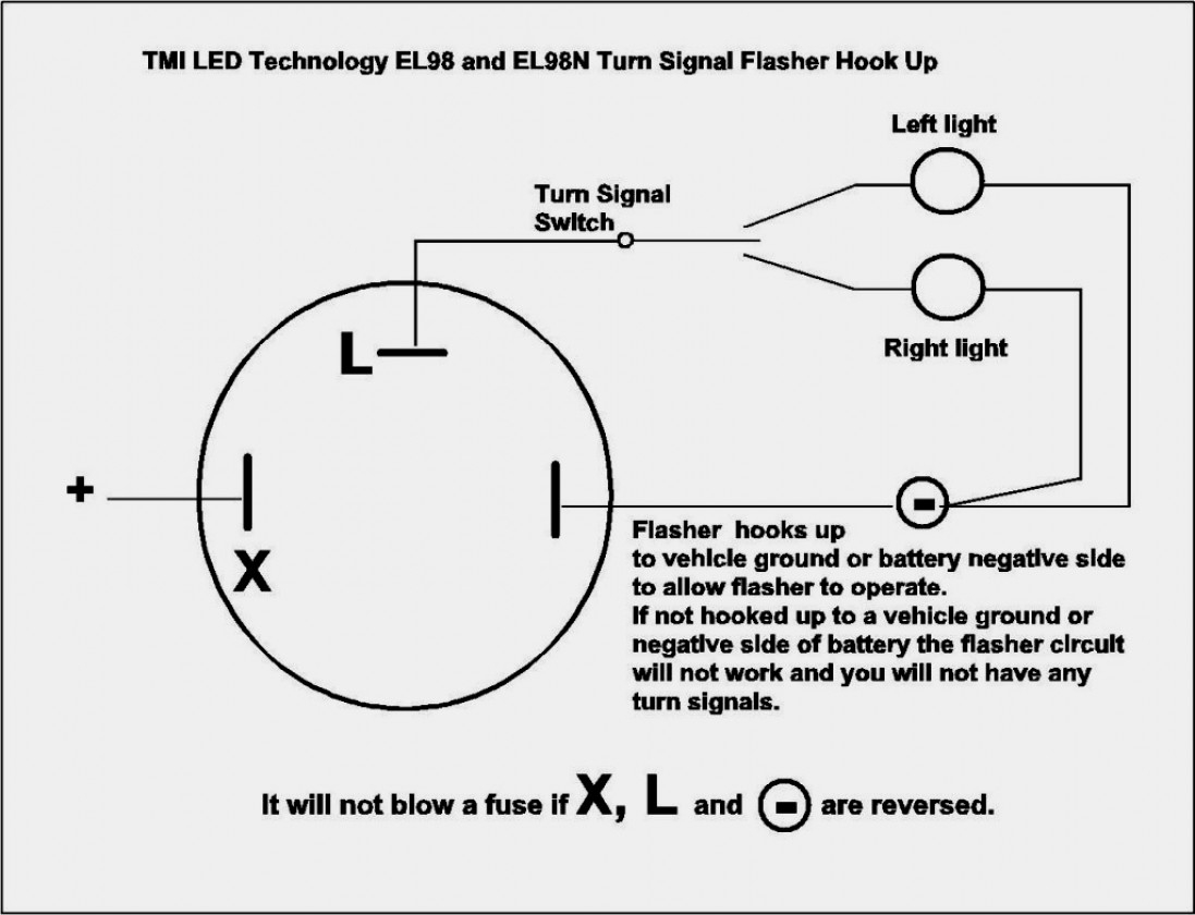
2 Pin Flasher Relay Wiring Diagram Wiring Diagram

Wiring Diagram For 2 Pin Flasher Relay Wiring Diagram
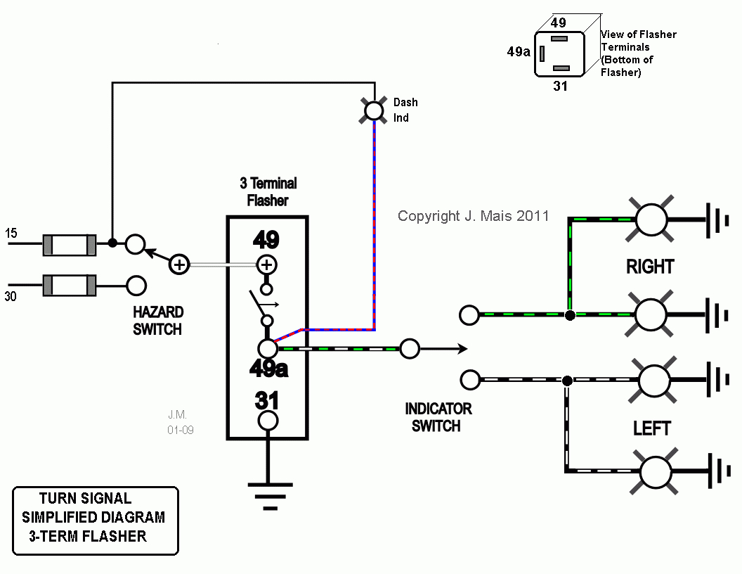
2 Pin Flasher Relay Wiring Diagram Wiring Diagram
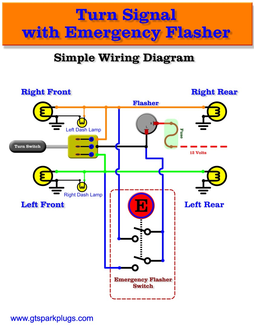
Turn Signal Flasher Wiring Diagram Wiring Diagram
70 Best Of 2 Pin Flasher Relay Wiring Diagram
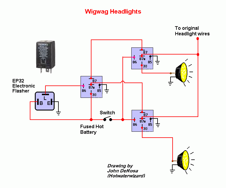
2 Pin Flasher Relay Wiring Diagram Manual 8

2 Pin Flasher Relay Wiring Diagram Wiring Diagram

2 Prong Flasher Wiring Diagram 14
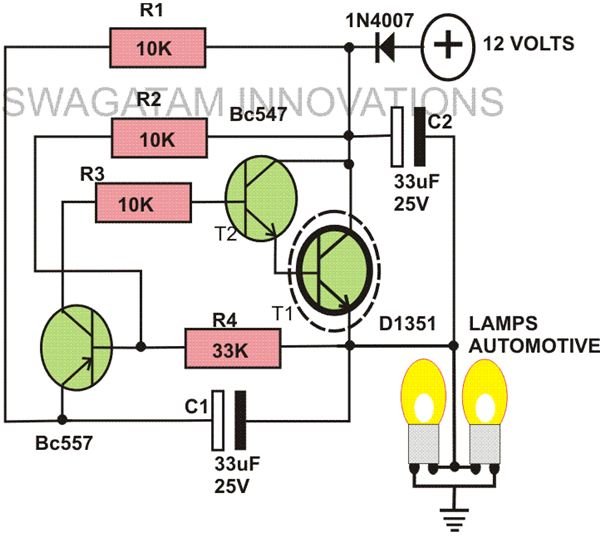
Wiring Diagram 2 Pin Flasher Relay Wiring Diagram
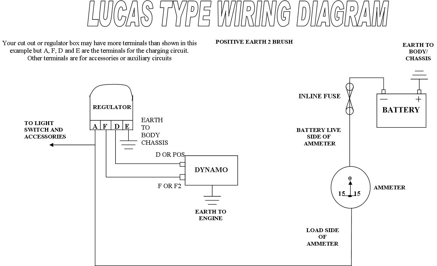
2 Pin Flasher Relay Wiring Diagram Wiring Diagram
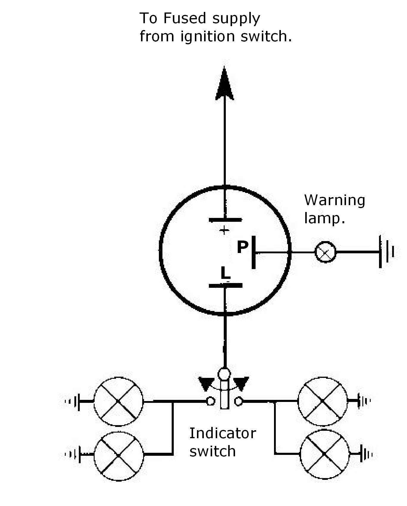
2 Pin Flasher Relay Wiring Diagram My Wiring DIagram
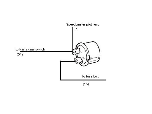
Beetle 19581967 View topic Wiring for a 2 prong relay
Wiring Diagram 2 Pin Flasher Relay Wiring Diagram

Flasher Unit Wiring Diagram 2 Pin Wiring Diagram


